Concept
The concept of this audio-visual work was an interactive representation of a band. All the band members (aka the three Arduinos) had distinct personalities and reacted differently to the interaction with the audience. The band consists of three members.
The Master/Drummer keeps the beat and sends information to the other band members on how to react to the crowd. The drummer would get faster with people around and slower with no audience.
Slave 1 / Guitar: The guitar takes in info from the master, telling him how busy it is in the area. The guitar then reacts to this information. When it’s quiet the guitar plays a simple sound, but with more people around the guitarist turns into a show off and plays more complex.
Slave 2 / Bass: The bass takes in info from the master, telling him how busy it is in the area. The bass then reacts to this information. When it’s quiet the bass plays normally, but when busy the bass plays quieter, as if its stage shy.
Circuit
Through labs in Performance Technology 2, in which we learned all the basics of Arduino, we were introduced to many tools that could be used in this final project. Arduino Unos use sensors to receive information from its environment, and then affects its surroundings by controlling lights, speaker’s motors and many other tools. We had to take into consideration our set guidelines, which included using multiple Arduinos communicating via I2C (the network). From the beginning we knew we wanted to incorporate sound and light outputs, and a motion type sensor for our input, and so we began to pick what we would need.
We began with choosing how we would gather information from the surrounding area, and so we decided to use an IR (Infrared) sensor, as seen in Figure 1.
as we were familiar with its. What an IR sensor does is a sensor scans IR signals in specific frequency ranges defined by standards and converts them to electric signals on its signal pin. When something was to stand in from of the sensor, the signal values would change, and so telling the code that something/ someone is closer to it. This was perfect for our use as we needed a sensor that could tell us if people were walking passed our piece.
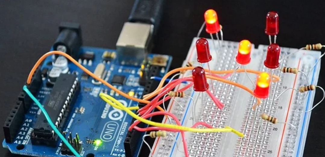
Next, we focused on what LEDs we wanted to use. We were already familiar with regular LEDs, we were then introduced to RGB LED’s. We decided that these would be a better option as we could control multiple colours though one LED and we had a wider range of colours to work from. For sound, we were only familiar with piezos, and so we decided on these. Along with all these we had to gather other equipment, including resistors, wires, and breadboards.
Once we had tested our circuit with our code and had it all working accordingly, we began reinforcing it, by soldering certain pieces together. Soldering is the act of fusing circuits together using solder. Using the soldering lab in CSIS, we began by soldering our RGB LED’s to copper board. Also, on this copper board was three resistors and wire, at the required length. We made three identical LED copper board setups. As seen in Figure 2. For both our three piezos and our IR sensor, we simply use soldered the wire ends onto neater pins, making them easier to put together. We also had to take into consideration the length of the wires we were using, as we had designed our piece to be in 5 different boxes, so we measured where each would be, and cut them accordingly. Once everything was neatly we began assembling the circuit into our boxes, which design is outlined within in this report.
The Code
To begin, the coding was simplified as much as possible. The main aim was to get the basic idea perfected and on completing this, make the piece more sophisticated. The first phase was to secure Arduino communication. A new function ‘myHandler’ was used to read the value of ‘x’ coming from the Master through ‘Wire.read()’ and this value dictated which path the Arduino would take. This can be seen in Figure 3.
Once the slaves had the ability to receive numbers the analogy read was included to take a value from the sensor. A serial print of this value was included to avoid any hardware issues.
Parameters were then set to identify when an object came within a certain distance of the sensor and these became the conditional statement for the control structure chosen; the if statement. The Tone function was utilised to create the sound for the installation. By adding the pitches library, it enabled us to choose specific notes by name instead of frequency and in turn create melodies. As the piezo’s sound wasn’t very appealing we changed to a click sound by reducing the delay between tones. To indicate movement under the speakers the delay was reduced further to speed up the clicks.
The RGB LEDs used were common anode which indicated they needed 5v instead of ground, this also signified the RGB values we wanted had to be subtracted from 255 for the required colour to be displayed. This can be seen in Figure 4. A for loop was used to imitate the desired blinking effect. The loop added 1 to the chosen Red, Green or Blue value, until it reached 255 and the loop began at 0 again, as seen in Figure 5. When this was done quickly it appeared like a blink which flashed in time with the sound as the delay on the Tone function affected both.
As the desired final piece had the three Arduino’s lights and piezo’s in sync, we attempted to use the millis function to avoid delays. Unfortunately, we simply couldn’t get this working and instead decided to reduce the amount of delays in the original code to improve our problem. This also made the task of personalising each Arduino quite difficult, so we had to sacrifice certain aspects of our original idea.
Design Process
Went through several design ideas before ending up with our final one. Our final design was a compromise between the aesthetic look decided on, and the practical limitations, skill level and resources available. We started off with a minimalistic design idea.
We wanted the sounds and lights in our work to be intentional and reflect the personalities of the band members. The colours chosen for the lights were meant to showcase the emotion of the band member, for example, the bassist turned blue with a larger crowd to showcase shyness and the guitarist turned red to showcase passion. The sounds were meant to complement the lights and be in sync with the desired emotion we wanted to convey.
Idea 1: Our first version of the design was a very simple and minimalistic approach We wanted the focus to be on the sound and lights and not so much on the shape or other characteristics of the work. (Figure 6)
Idea 2: After thinking about the specific aesthetic more, we decided that we wanted to have all the Arduinos hanging in separate pyramid shapes to create more of an interesting look. The three pyramids reminded us of hanging lights, we also wanted to incorporate symbols for each of the different instruments. (Figure 7)
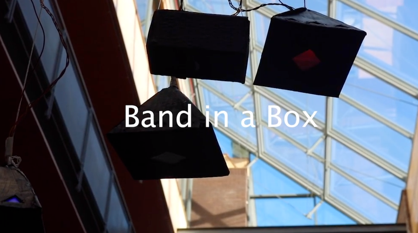
Idea 3: For the final version of our project we ended up painting all the cardboard black and making cut out shapes into the sides to make the RGB lights show better. We also added parchment paper over the cut-outs to even out the light coming through. Our final design had the sensor hanging in a separate box along with the three pyramid shapes with the RGBs and piezos and the Arduinos and bulk of the wires were in a larger box above them. (Figure 8)
Final Piece & Installing
We were happy with the way the project turned out, even with some small mishaps on the way. We didn’t get bigger speakers than the piezos until the very morning of the project installation, with limited time before needing to showcase our work. We tried to solder the larger audio output devices to wires and connect them to our project. Unfortunately, we didn’t manage to get them to work and went back to using the piezos for the performance. Another unexpected situation occurred when our project, which was hanging from the CSIS atrium, fell a few hours after hanging it up. We managed to get it back up, but some damage was done to the wires and the aesthetics of the cardboard.
Overall, we all gained valuable skills in coding, hardware, soldering, design and teamwork. The project made us use the technical skills we learned throughout the module in a creative and more abstract way. With a project like this time management and attention to detail are things that we learned to focus more heavily on in future projects. Our final piece can be seen in Figure 8.